10. Synthesis, Timing and Gate-Level Verification

About the animals in this picture and where they are standing
- Markhor (Capra falconeri) lives in the mountains of Pakistan, Afghanistan and neighbouring regions. The males' horns twist in a corkscrew; the name is often explained as Persian for 'snake-eater'. It is Pakistan's national animal, and community-based conservation has helped some populations recover.
- Nubian ibex (Capra nubiana) lives in the rocky, arid hills of north-east Africa and the Arabian Peninsula, from the Sinai and Egypt south to Sudan and Ethiopia. Its coat matches the desert rock, and the males' ridged horns sweep back like a sickle.
- Siberian ibex (Capra sibirica) lives in the high mountains of Central Asia, from the Altai and Tian Shan to the Himalaya. It is one of the largest ibexes, and the males' ridged horns can exceed a metre in length.
- Walia ibex (Capra walie) lives nowhere but the Simien Mountains of northern Ethiopia, on high cliffs. It is endangered, with only a few hundred animals remaining, and is protected within the Simien Mountains National Park.
The scene is imaginary: it is set on Triton, Neptune's largest moon: it orbits backward and has nitrogen geysers. The animals are stylised drawings, shown where they could not live, for effect.
What you will understand: what happens between "the Verilog passes its tests" and "there is a netlist of gates you could manufacture": synthesis to a standard-cell library, area and timing read off the result, and the three ways a chip team checks that the netlist still does what the RTL did: gate-level simulation, fault grading, and equivalence checking. Along the way the flow hits a famous trap (X-pessimism) and the tests find a bug in the testbench.
What you need to know first: Chapters 1-9. Appendix G (the EDA flow) is the background on synthesis, libraries and timing. Every number below is for a toy cell library invented for this book (areas in NAND2 equivalents, one made-up delay per cell). It is a scale for comparing designs and a way to exercise a real flow, not a process: no number here predicts a real chip's area, speed or power.
What this chapter builds: tools/gen_toylib.py (the toy library), tools/synth.py (the Yosys flow and a 60-line static timing analyzer), tools/netlist.py and tools/ch10_faults.py (fault grading and test generation), tools/ch10_run.py, tools/mut_ch10.py, and for the running examples rtl/demo_add.v, tb/demo_add_tb.v, rtl/requant_p2.v, tb/requant_p2_tb.v, tb/requant_p2k_tb.v, tools/ch10_example_a.py and tools/ch10_example_b.py.
Why this chapter: "it passes the tests" is not "it can be built"
Until now the circuits were descriptions: they simulate correctly, and Yosys has given us gate counts. A chip needs more. It needs a netlist mapped onto the cells the factory's library actually provides, an answer to "how fast can the clock run?", and some evidence that the netlist still does what the RTL did. Each of those is a place where a correct design can go wrong without anyone writing a bug: the optimizer is not perfect, the simulator can be too pessimistic, and the tests may never have exercised half the gates.
Two questions organize the chapter. How fast, and what sets the clock? (timing) and are we sure? (verification of the netlist). The two examples at the end answer the first with experiments you can change and rerun.
The flow
Synthesis turns the RTL into a netlist: a graph of library cells and flip-flops.
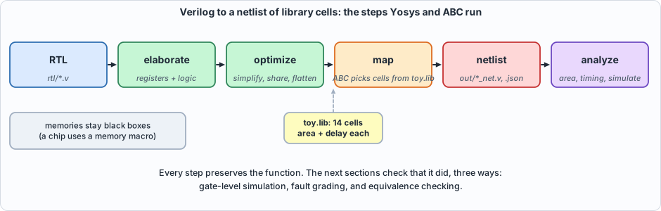 Figure 10.1: the flow. Mapping chooses cells from the library; the netlist is then analysed and simulated.
RTL (Verilog)  --elaborate-->  logic + registers  --optimize-->  --map to cells-->  netlist
                                                                    (Yosys + ABC, toy library)
Memories are not synthesized into flip-flops: a chip uses a memory compiler's macro. Here the scratchpad and the operand memories stay as black boxes in the netlist and are simulated by their behavioural models.
The toy library: tools/gen_toylib.py
#!/usr/bin/env python3
"""Chapter 10: generate the book's TOY standard-cell library: lib/toy.lib (for synthesis and area/delay) and lib/toy_cells.v (simulation models for gate-level simulation), from ONE table so they cannot disagree.
Areas are in NAND2 equivalents ('gate equivalents', GE), using typical textbook ratios; delays are one made-up number per cell in ns. It is NOT any real process: it is a scale for comparing designs and a way to exercise the flow. Usage: gen_toylib.py"""
import os
ROOT = os.path.dirname(os.path.dirname(os.path.abspath(__file__)))
CELLS = [  # name, inputs, function (liberty syntax), verilog expression, area (NAND2 = 1.0), delay (ns, one value for every input)
 ("BUF",   ["A"], "A", "A", 1.00, 0.08), ("INV",   ["A"], "!A", "~A", 0.67, 0.04),
 ("NAND2", ["A","B"], "!(A&B)", "~(A & B)", 1.00, 0.07), ("NOR2",  ["A","B"], "!(A|B)", "~(A | B)", 1.00, 0.09),
 ("AND2",  ["A","B"], "(A&B)", "A & B", 1.33, 0.11), ("OR2",   ["A","B"], "(A|B)", "A | B", 1.33, 0.13),
 ("XOR2",  ["A","B"], "(A^B)", "A ^ B", 2.00, 0.16), ("XNOR2", ["A","B"], "!(A^B)", "~(A ^ B)", 2.00, 0.16),
 ("NAND3", ["A","B","C"], "!(A&B&C)", "~(A & B & C)", 1.50, 0.10), ("NOR3",  ["A","B","C"], "!(A|B|C)", "~(A | B | C)", 1.50, 0.13),
 ("AOI21", ["A","B","C"], "!((A&B)|C)", "~((A & B) | C)", 1.67, 0.11), ("OAI21", ["A","B","C"], "!((A|B)&C)", "~((A | B) & C)", 1.67, 0.11),
 ("MUX2",  ["A","B","S"], "((S&B)|(!S&A))", "S ? B : A", 2.33, 0.18),
]
DFF_AREA, DFF_CLK_TO_Q = 5.00, 0.30
lib = ['/* A TOY standard-cell library for the book (generated by tools/gen_toylib.py). Areas in NAND2 equivalents, delays in ns, both made up from textbook ratios. NOT any real process. */',
       'library(toy) {', '  delay_model : table_lookup;', '  time_unit : "1ns";', '  capacitive_load_unit(1, pf);', '  voltage_unit : "1V";', '  current_unit : "1mA";', '  pulling_resistance_unit : "1kohm";',
       '  lu_table_template(scalar) { variable_1 : input_net_transition; index_1("0"); }']
for n, ins, fn, v, a, d in CELLS:
    lib += [f'  cell({n}) {{', f'    area : {a};']
    for p in ins: lib.append(f'    pin({p}) {{ direction : input; capacitance : 0.01; }}')
    lib += ['    pin(Y) {', '      direction : output;', f'      function : "{fn}";']
    for p in ins: lib.append(f'      timing() {{ related_pin : "{p}"; timing_sense : non_unate; cell_rise(scalar) {{ values("{d}"); }} cell_fall(scalar) {{ values("{d}"); }} rise_transition(scalar) {{ values("0.01"); }} fall_transition(scalar) {{ values("0.01"); }} }}')
    lib += ['    }', '  }']
lib += ['  cell(DFF) {', f'    area : {DFF_AREA};', '    ff(IQ, IQN) { clocked_on : "CK"; next_state : "D"; }', '    pin(D) { direction : input; capacitance : 0.01; }', '    pin(CK) { direction : input; clock : true; capacitance : 0.01; }',
        f'    pin(Q) {{ direction : output; function : "IQ"; timing() {{ related_pin : "CK"; timing_type : rising_edge; cell_rise(scalar) {{ values("{DFF_CLK_TO_Q}"); }} cell_fall(scalar) {{ values("{DFF_CLK_TO_Q}"); }} rise_transition(scalar) {{ values("0.01"); }} fall_transition(scalar) {{ values("0.01"); }} }} }}', '  }', '}']
os.makedirs(os.path.join(ROOT, "lib"), exist_ok=True)
open(os.path.join(ROOT, "lib", "toy.lib"), "w").write("\n".join(lib) + "\n")
v = ["// Simulation models of the toy library (generated together with lib/toy.lib by tools/gen_toylib.py)."]
for n, ins, fn, ex, a, d in CELLS: v.append(f"module {n}({', '.join('input ' + p for p in ins)}, output Y); assign Y = {ex}; endmodule")
v.append("module DFF(input D, input CK, output reg Q);\n`ifdef POWERUP_ZERO\n    initial Q = 1'b0;      // a defined power-up state (real flip-flops power up to 0 or 1, unpredictably)\n`endif\n    always @(posedge CK) Q <= D;\nendmodule")
open(os.path.join(ROOT, "lib", "toy_cells.v"), "w").write("\n".join(v) + "\n"); print(f"lib/toy.lib and lib/toy_cells.v written: {len(CELLS)} combinational cells and one flip-flop")
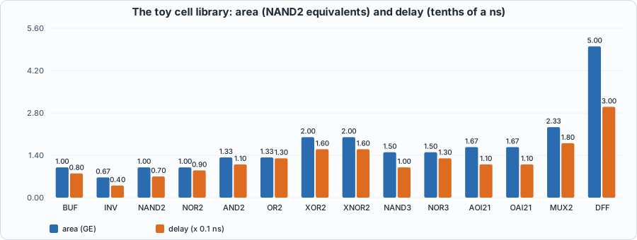 Figure 10.2: the toy library: a NAND2 is the unit of area (1.0); an XOR is twice as big and about twice as slow; a flip-flop is five NAND2s.
One table generates both the file synthesis reads (lib/toy.lib) and the simulation models (lib/toy_cells.v), so the two cannot disagree. (Chapter 10's mutation run deliberately breaks that guarantee to see if the tests notice.)
The flow and a small timing analyzer: tools/synth.py
#!/usr/bin/env python3
"""Chapter 10: the synthesis flow and a small static timing analyzer.
  synth(files, top, tag, memories=())   run Yosys: read the RTL (memories are kept as black boxes, as a chip uses a memory compiler's macros), elaborate, optimize, map to the toy cell library (lib/toy.lib),
                                        write out/<tag>_net.v (a Verilog netlist of toy cells) and out/<tag>_net.json; returns area, cell counts and the log.
  sta(json_path, top)                   the longest register-to-register (or input/output) path through the netlist, in ns, using the library's delays and these macro assumptions: a synchronous memory's data output appears
                                        MACRO_CLK_TO_Q after the clock; an asynchronous memory read takes MACRO_READ from address to data; everything entering a memory or a flip-flop must arrive SETUP before the clock.
The analyzer is ~60 lines: it adds up cell delays along the longest path, ignoring wires, fan-out and clock skew. It is a model of timing, not a signoff tool."""
import json, os, re, subprocess, sys
ROOT = os.path.dirname(os.path.dirname(os.path.abspath(__file__)))
SETUP, MACRO_CLK_TO_Q, MACRO_READ, DFF_CLK_TO_Q = 0.10, 0.50, 0.40, 0.30
def lib_delays():
    txt = open(os.path.join(ROOT, "lib", "toy.lib")).read(); d = {}
    for m in re.finditer(r"cell\((\w+)\) \{(.*?)\n  \}", txt, re.S):
        v = re.search(r'cell_rise\(scalar\) \{ values\("([\d.]+)"\)', m.group(2)); d[m.group(1)] = float(v.group(1)) if v else None
    return d
def synth(files, top, tag, memories=(), lib="lib/toy.lib"):
    out = os.path.join(ROOT, "out"); script = []
    if memories: script.append("read_verilog -sv -lib " + " ".join(memories))
    script += ["read_verilog -sv " + " ".join(files), f"hierarchy -top {top}", f"synth -flatten -top {top}", "dfflegalize -cell $_DFF_P_ x", f"dfflibmap -liberty {lib}", f"abc -liberty {lib}", "opt_clean -purge",
               f"tee -o out/{tag}_stat.txt stat -liberty {lib}", f"write_verilog -noattr out/{tag}_net.v", f"write_json out/{tag}_net.json"]
    p = subprocess.run(["yosys", "-q", "-l", f"out/{tag}_synth.log", "-p", "; ".join(script)], cwd=ROOT, capture_output=True, text=True)
    if p.returncode != 0: return {"ok": False, "log": p.stdout + p.stderr}
    stat = open(os.path.join(out, f"{tag}_stat.txt")).read()
    cells = {m.group(1): int(m.group(2)) for m in re.finditer(r"^\s+(\w+)\s+(\d+)\s*$", stat.split("Number of cells")[1], re.M)} if "Number of cells" in stat else {}
    area = re.search(r"Chip area for (?:top )?module '\\?\w+': ([\d.]+)", stat)
    return {"ok": True, "area": float(area.group(1)) if area else None, "cells": cells, "ncells": sum(cells.values()), "stat": stat}
def sta(json_path, top):
    delays = lib_delays(); mod = json.load(open(json_path))["modules"][top]; ports = mod["ports"]; cells = mod["cells"]
    driver = {}; endpoints = []          # bit -> (cell name, delay, [input bits])  ; endpoints: (bit, extra)
    arrivals = {}
    for name, c in cells.items():
        t = c["type"]; dirs = c.get("port_directions", {}); conn = c["connections"]
        if t == "DFF":
            driver[conn["Q"][0]] = (name, DFF_CLK_TO_Q, []); endpoints.append((conn["D"][0], name + ".D"))
        elif t in delays and delays[t] is not None:
            ins = [b for pn, bits in conn.items() if pn != "Y" for b in bits]
            for b in conn["Y"]: driver[b] = (name, delays[t], ins)
        else:                            # a memory macro (black box)
            outs = [pn for pn, dr in dirs.items() if dr == "output"]; ins = [pn for pn, dr in dirs.items() if dr == "input"]
            if t == "rowmem":
                ra = [b for b in conn["raddr"]]
                for b in conn["rdata"]: driver[b] = (name + ".read", MACRO_READ, ra)
                for pn in ("we", "waddr", "wdata"): endpoints += [(b, name + "." + pn) for b in conn[pn]]
            else:
                for pn in outs:
                    for b in conn[pn]: driver[b] = (name + "." + pn, MACRO_CLK_TO_Q, [])
                endpoints += [(b, name + "." + pn) for pn in ins if pn not in ("clk",) for b in conn[pn]]
    for pn, p in ports.items():
        if p["direction"] == "output": endpoints += [(b, "output " + pn) for b in p["bits"]]
    sys.setrecursionlimit(1000000); pred = {}
    def arr(b):
        if not isinstance(b, int): return 0.0
        if b in arrivals: return arrivals[b]
        if b not in driver: arrivals[b] = 0.0; return 0.0           # a primary input
        nm, d, ins = driver[b]; best = 0.0; bp = None
        for i in ins:
            a = arr(i)
            if a >= best: best, bp = a, i
        arrivals[b] = best + d; pred[b] = (nm, bp); return arrivals[b]
    worst, wb, wname = -1.0, None, ""
    for b, nm in endpoints:
        if isinstance(b, int):
            a = arr(b)
            if a > worst: worst, wb, wname = a, b, nm
    path = []; b = wb
    while isinstance(b, int) and b in pred: nm, b2 = pred[b]; path.append(nm); b = b2
    return {"critical_ns": worst + SETUP, "endpoint": wname, "depth": sum(1 for p in path if not p.endswith(".read")), "path_head": list(reversed(path))[:6]}
if __name__ == "__main__":
    r = synth(["rtl/requant.v"], "requant", "requant"); print(r["area"], r["ncells"], sta(os.path.join(ROOT, "out", "requant_net.json"), "requant"))
synth runs Yosys: elaborate, optimize, flatten, legalize the flip-flops, map them and the logic to the toy library, write a Verilog netlist and a JSON netlist. sta is a static timing analyzer in 60 lines: it adds up cell delays along the longest path between flip-flops (or macros, or ports). It ignores wires, fan-out and clock skew. How to read timing. Every path starts at a flip-flop (or an input) and ends at a flip-flop (or an output). Its delay is the clock-to-q of the starting flip-flop, plus the delay of each gate on the way, plus the setup time of the end. The slowest path sets the clock period: the clock cannot tick faster than the signal can cross it. A cell's delay depends on what it is, a gate's depth is how many cells deep the path is, and a design is as fast as its slowest path, however fast the rest is. Is the analyzer right? It is checked on a circuit small enough to do by hand:
== 2. is the timing analyzer right? a hand-built circuit: y = INV(NAND2(INV(a), a)); q = DFF(NAND2(...)); z = INV(q)
  by hand: y path 0.04+0.07+0.04 = 0.15, +0.10 setup = 0.25; flop path 0.11+0.10 = 0.21; clock-to-q 0.30 + INV 0.04 + 0.10 = 0.44 -> worst 0.44 ns at output z
  analyzer: 0.44 ns at output z
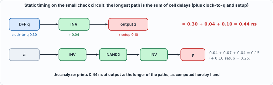 Figure 10.3: the hand check of the timing analyzer. The output z is reached through a flip-flop (0.30 clock-to-q), an inverter (0.04) and the 0.10 setup: 0.44 ns.
Results
#!/usr/bin/env python3
"""Chapter 10: the synthesis flow and gate-level verification of GA-2. Usage: ch10_run.py   (about 10 minutes: it simulates a 31,000-cell netlist several times)"""
import os, re, subprocess, sys
sys.path.insert(0, os.path.dirname(os.path.abspath(__file__))); sys.path.insert(0, os.path.join(os.path.dirname(os.path.abspath(__file__)), "..", "model"))
import hw, synth
R = hw.ROOT
def line(out): return ([l for l in out.splitlines() if l.startswith(("PASS", "FAIL", "MISMATCH"))] or out.strip().splitlines()[-2:])[0]
print("== 1. the toy cell library (lib/toy.lib, made by tools/gen_toylib.py): area in NAND2 equivalents, delay in ns")
txt = open(os.path.join(R, "lib", "toy.lib")).read()
for m in re.finditer(r"cell\((\w+)\) \{\n    area : ([\d.]+);", txt):
    d = re.search(r'cell_rise\(scalar\) \{ values\("([\d.]+)"\)', txt[m.end():]).group(1); print(f"  {m.group(1):6s} area {m.group(2):>5s}   delay {d} ns")
print("\n== 2. is the timing analyzer right? a hand-built circuit: y = INV(NAND2(INV(a), a)); q = DFF(NAND2(...)); z = INV(q)")
subprocess.run(["yosys", "-q", "-p", "read_verilog -sv lib/toy_cells.v lib/chain_check.v; hierarchy -top chain; proc; write_json out/chain_net.json"], cwd=R)
r = synth.sta(os.path.join(R, "out", "chain_net.json"), "chain")
print(f"  by hand: y path 0.04+0.07+0.04 = 0.15, +0.10 setup = 0.25; flop path 0.11+0.10 = 0.21; clock-to-q 0.30 + INV 0.04 + 0.10 = 0.44 -> worst 0.44 ns at output z")
print(f"  analyzer: {r['critical_ns']:.2f} ns at {r['endpoint']}")
print("\n== 3. synthesize every unit and the whole chip (memories stay as macros)")
RT = ["rtl/dma.v", "rtl/systolic.v", "rtl/requant.v", "rtl/exp_lut.v", "rtl/divu.v", "rtl/ga2_vec.v", "rtl/ga2_sm.v", "rtl/ga2_mm.v", "rtl/ga2.v"]; MEM = ["rtl/sram.v", "rtl/rowmem.v"]
print(f"{'unit':10s} {'cells':>7s} {'area (GE)':>10s} {'flip-flops':>11s} {'critical path':>14s} {'gate depth':>11s} {'max clock':>10s}  critical endpoint")
for top in ("exp_lut", "divu", "requant", "systolic", "ga2_st", "ga2_rq", "ga2_vadd", "ga2_amax", "ga2_sm", "ga2_mm", "ga2"):
    s = synth.synth(RT, top, top, memories=MEM)
    if not s["ok"]: print(top, "FAILED", s["log"][-300:]); continue
    t = synth.sta(os.path.join(R, "out", top + "_net.json"), top); ff = s["cells"].get("DFF", 0)
    print(f"{top:10s} {s['ncells']:7d} {s['area']:10.0f} {ff:11d} {t['critical_ns']:11.2f} ns {t['depth']:11d} {1000/t['critical_ns']:7.0f} MHz  {t['endpoint']}")
print("\n== 4. gate-level simulation of the whole chip: the SAME testbench and program suite, now driving the netlist of toy cells (memories as behavioural macros)")
G = ["lib/toy_cells.v", "rtl/sram.v", "rtl/rowmem.v", "out/ga2_net.v", "tb/extmem_rw.v", "tb/ga2_tb.v"]
print(subprocess.run([sys.executable, "model/ga2_progs.py", "out/ga2_programs.hex", "60", "1"], cwd=R, capture_output=True, text=True).stdout.strip(), "(78 programs)")
rc, out = hw.sim_verilator(G, "ga2_tb"); print(f"  Verilator, netlist, all 78 programs        : {line(out)} (exit {rc})")
print(subprocess.run([sys.executable, "model/ga2_progs.py", "out/ga2_programs.hex", "12", "3"], cwd=R, capture_output=True, text=True).stdout.strip(), "(30 programs, for the slower runs below)")
rc, out = hw.sim_icarus(G, "ga2_tb"); print(f"  Icarus (4-state), flip-flops start as x     : {line(out)} (exit {rc})")
rc, out = hw.sim_icarus(G, "ga2_tb", defines=("POWERUP_ZERO",)); print(f"  Icarus (4-state), flip-flops start at 0     : {line(out)} (exit {rc})")
for seed in (1, 2, 3):
    rc, out = hw.sim_verilator(G, "ga2_tb", args=("--x-initial", "unique", "--x-assign", "unique"), runargs=("+verilator+rand+reset+2", f"+verilator+seed+{seed}")); print(f"  Verilator, random power-up state, seed {seed}  : {line(out)} (exit {rc})")
Output (cloud sandbox -- live-executed; Yosys 0.33, Icarus Verilog 12.0, Verilator 5.020)
== 1. the toy cell library (lib/toy.lib, made by tools/gen_toylib.py): area in NAND2 equivalents, delay in ns
  BUF    area   1.0   delay 0.08 ns
  INV    area  0.67   delay 0.04 ns
  NAND2  area   1.0   delay 0.07 ns
  NOR2   area   1.0   delay 0.09 ns
  AND2   area  1.33   delay 0.11 ns
  OR2    area  1.33   delay 0.13 ns
  XOR2   area   2.0   delay 0.16 ns
  XNOR2  area   2.0   delay 0.16 ns
  NAND3  area   1.5   delay 0.1 ns
  NOR3   area   1.5   delay 0.13 ns
  AOI21  area  1.67   delay 0.11 ns
  OAI21  area  1.67   delay 0.11 ns
  MUX2   area  2.33   delay 0.18 ns
  DFF    area   5.0   delay 0.3 ns

== 2. is the timing analyzer right? a hand-built circuit: y = INV(NAND2(INV(a), a)); q = DFF(NAND2(...)); z = INV(q)
  by hand: y path 0.04+0.07+0.04 = 0.15, +0.10 setup = 0.25; flop path 0.11+0.10 = 0.21; clock-to-q 0.30 + INV 0.04 + 0.10 = 0.44 -> worst 0.44 ns at output z
  analyzer: 0.44 ns at output z

== 3. synthesize every unit and the whole chip (memories stay as macros)
unit         cells  area (GE)  flip-flops  critical path  gate depth  max clock  critical endpoint
exp_lut        376        522           0        1.16 ns           8     862 MHz  output e
divu          1253       2638         249        2.06 ns          14     485 MHz  $auto$ff.cc:266:slice$894.D
requant       5403       7881           0        9.87 ns          79     101 MHz  output q
systolic     15782      26118         704        5.22 ns          40     192 MHz  $auto$ff.cc:266:slice$1236.D
ga2_st         427        884          67        2.11 ns          16     474 MHz  $auto$ff.cc:266:slice$798.D
ga2_rq        5858       8919          94        9.92 ns          80     101 MHz  output wd
ga2_vadd       596       1233          93        2.18 ns          16     459 MHz  output ra
ga2_amax       575       1249         108        2.06 ns          16     485 MHz  output ra
ga2_sm        4843       8074         309        5.02 ns          39     199 MHz  output wd
ga2_mm       12134      21159         875        5.88 ns          42     170 MHz  $auto$ff.cc:266:slice$3714.D
ga2          31580      53526        1987       10.47 ns          81      96 MHz  sp.wdata

== 4. gate-level simulation of the whole chip: the SAME testbench and program suite, now driving the netlist of toy cells (memories as behavioural macros)
78 programs written to out/ga2_programs.hex (18 directed, 60 random) (78 programs)
  Verilator, netlist, all 78 programs        : PASS: 78 programs match the Python reference (memory and all five cycle counters), 219583 cycles in total (exit status 0) (exit 0)
30 programs written to out/ga2_programs.hex (18 directed, 12 random) (30 programs, for the slower runs below)
  Icarus (4-state), flip-flops start as x     : MISMATCH program 0 ext[1024]: got 0 want fffffff9 (exit 1)
  Icarus (4-state), flip-flops start at 0     : PASS: 30 programs match the Python reference (memory and all five cycle counters), 60832 cycles in total (exit status 0) (exit 0)
  Verilator, random power-up state, seed 1  : PASS: 30 programs match the Python reference (memory and all five cycle counters), 60832 cycles in total (exit status 0) (exit 0)
  Verilator, random power-up state, seed 2  : PASS: 30 programs match the Python reference (memory and all five cycle counters), 60832 cycles in total (exit status 0) (exit 0)
  Verilator, random power-up state, seed 3  : PASS: 30 programs match the Python reference (memory and all five cycle counters), 60832 cycles in total (exit status 0) (exit 0)
Reading it
- Area. The whole chip, apart from its memories, is 31,580 cells: 53,526 NAND2 equivalents and 1,987 flip-flops. The biggest pieces are the matrix unit (21,159 GE, containing the 4 x 4 array), the softmax unit (8,074) and the requantizer (7,881, and again inside
RQ). The array synthesized on its own comes out larger (26,118 GE) than the matrix unit that contains it; the reason was not investigated (plausibly, outputs that the matrix unit never uses are pruned there). The 4,096 x 32-bit scratchpad is not in the count: it is a macro. - Timing. The longest path in the whole chip is 10.47 ns (81 gates deep), about 96 MHz in this toy library, and it ends at the scratchpad's write data. It begins at the scratchpad's read data: the path scratchpad read -> requantizer -> scratchpad write, all in one cycle. The requantizer alone is 79 gates deep (9.87 ns): the 32 x 24-bit multiplier, the rounding adder, the shifter and the clamp are all in one combinational stretch. Every other unit is 2 to 6 ns. One unit sets the clock for the whole chip. The fix real designs make is to pipeline it, with a register in the middle and an extra cycle of latency. Running example B below does that experimentally, and finds that where the register goes, and what else is on the path, matter more than one might expect: a first attempt, cutting after the multiplier, gains only 1.11x, and the cure turns out to be a faster adder.
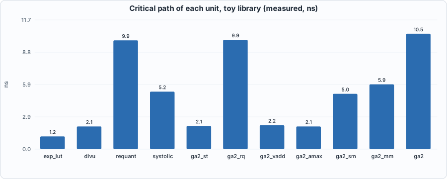 Figure 10.4 (measured): critical path by unit. The requantizer (9.9 ns) and the RQ unit that wraps it are far above every other unit; the chip's 10.5 ns is their path plus the scratchpad's access time.
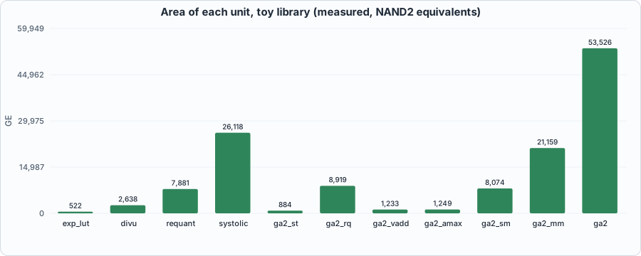 Figure 10.5 (measured): area by unit. The array and the matrix unit dominate; the requantizer is the biggest vector unit.
- Registers. Only the units with state have flip-flops (the divider's 249 are its numerator, quotient and remainder).
Gate-level simulation: the same tests on the netlist
The strongest cheap check that synthesis did not change behaviour is to run the same testbench and the same programs on the netlist. The gate-level run drives the netlist of toy cells with Chapter 7's 78-program suite and compares memory and all five cycle counters with the Python reference. In Verilator it passes: the synthesized chip takes exactly the same cycles and produces exactly the same memory (219,583 cycles; the netlist now includes the UNPACK unit of Chapter 13). It runs slowly (about two minutes in Verilator for the whole suite, five in Icarus): a 31,000-cell netlist is a lot to evaluate.
The trap: X-pessimism
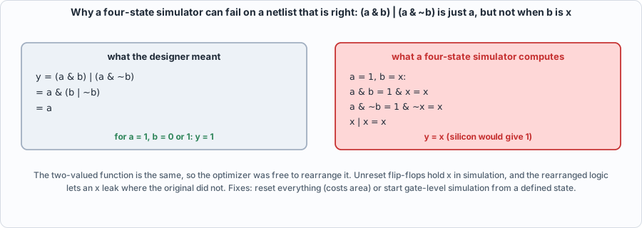 Figure 10.6: the mechanism. The expression is just
a, but evaluating each piece with an unknown b gives x.
In Icarus the same netlist fails from the very first program, with the external memory left unchanged. Verilator passes. The cause is not a logic error, and the evidence is that giving the flip-flops a defined power-up value (the POWERUP_ZERO option of the cell model) makes Icarus pass the same programs with the same counters.
Icarus is four-state (0, 1, x, z). In the RTL, registers that are not reset simply hold x until the first time they are loaded, and nothing reads them before that. After synthesis, the logic has been rearranged by an optimizer that only had to preserve the two-valued function. A rearrangement that is equivalent for 0 and 1 may not be for x: for example (a & b) | (a & ~b) is just a, but with b = x the unsimplified form evaluates to x. Idle units' unreset address registers therefore leak x into the scratchpad's write address. This is X-pessimism: the simulator is more pessimistic than silicon, which has a definite 0 or 1 in every flip-flop. Teams respond by resetting every flop (which costs area) or by starting gate-level simulations from a defined state. The book does the second and says so.
That raises a fair question: does the chip work from any power-up state? Verilator can start every register at a random value. With three different random seeds the 30-program suite passes each time.
A bug in the testbench. The first random power-up run (seed 1) failed. The symptom was a stray word deadbeef at the front of the data: the testbench's memory model returns that value for out-of-range addresses, and it had answered a request issued by the chip's random power-up state in the very first clock, before reset had taken effect. The answer arrived while the real first load was starting. A real memory system is reset with the chip, so the fix is in the testbench: the memory model now discards every request in flight when rst is high (tb/extmem_rw.v). The chip was right; the first test had been written for a world in which power-up state is always zero.
Fault grading: how good are the tests at the gate level?
A manufactured chip can have defects. The simplest model of one is a stuck-at fault: one gate output is permanently 0 or 1. A test set is judged by the fraction of faults it detects, meaning it makes some output differ from a good chip. This is the gate-level answer to the question mutation testing answered for the RTL.
#!/usr/bin/env python3
"""Chapter 10: how good are the tests at the GATE level? Stuck-at fault grading of the synthesized requantizer.
A stuck-at fault forces one gate output to a constant 0 or 1 (a manufacturing defect). A test set is judged by the fraction of faults it DETECTS, i.e. makes some output differ from the good circuit.
1. synthesize the requantizer to the toy library;  2. sample 150 gate outputs, giving 300 faults;  3. simulate them against the golden vectors (directed cases first, then random), recording the first vector that detects each;
4. for every fault never detected, ask ABC's equivalence checker whether the faulty circuit is equivalent to the good one (a REDUNDANT fault, which no test can detect) or not (a testable fault the vectors missed, for which it returns a distinguishing input).
Usage: ch10_faults.py"""
import os, random, re, subprocess, sys
sys.path.insert(0, os.path.dirname(os.path.abspath(__file__))); import hw, synth, netlist as N
R_ = hw.ROOT; NRAND = 40000
r = synth.synth(["rtl/requant.v"], "requant", "requant"); js = os.path.join(R_, "out", "requant_net.json")
all_nets = N.nets(js, "requant"); sites = random.Random(5).sample(all_nets, 150)
print(f"requantizer: {r['ncells']} gates, {r['area']:.0f} NAND2-equivalents; {len(all_nets)} gate outputs, {len(sites)} sampled, {2*len(sites)} stuck-at faults")
open(os.path.join(R_, "out", "requant_f.v"), "w").write(N.to_verilog_faultable(js, "requant", sites, "requant_f"))
out = subprocess.run([sys.executable, "model/requant_gold.py", "out/requant_vectors.hex", str(NRAND)], cwd=R_, capture_output=True, text=True).stdout.strip(); print(out)
nrows = int(open(os.path.join(R_, "out", "requant_vectors.hex")).readline(), 16); D = nrows - NRAND
rc, log = hw.sim_verilator(["lib/toy_cells.v", "out/requant_f.v", "tb/requant_fault_tb.v"], "requant_fault_tb", defines=(f"NFAULT={len(sites)}",))
assert "FAULTFREE ok" in log, log[-1500:]
first = {}
for m in re.finditer(r"FAULT (\d+) (\d+) (-?\d+)", log): first[(int(m.group(1)), int(m.group(2)))] = int(m.group(3))
print(f"\n== 1. fault coverage as the test set grows ({D} directed vectors come first, then random ones)")
print(f"{'vectors applied':>16s} {'detected':>9s} {'coverage':>9s}")
for k in (50, 200, D, D + 100, D + 1000, D + 10000, nrows):
    det = sum(1 for v in first.values() if 0 < v <= k); print(f"{k:16d} {det:9d} {100*det/len(first):8.2f}%" + ("   <- all directed vectors" if k == D else "   <- everything" if k == nrows else ""))
und = [f for f, v in first.items() if v < 0]
TIE = {"m_23": 1}          # operating constraint: the mantissa is normalized (2^23 <= m < 2^24), as everywhere in the book
print(f"\n== 2. the {len(und)} faults no vector detected: redundant, or a gap in the tests?  (equivalence checking with the input m[23] held at 1)")
red = 0; patterns = []
open("/tmp/ch10_good.blif", "w").write(N.to_blif(js, "requant", tie=TIE))
for (k, val) in und:
    open("/tmp/ch10_bad.blif", "w").write(N.to_blif(js, "requant", fault=(sites[k], val), tie=TIE))
    o = subprocess.run(["yosys-abc", "-c", "cec /tmp/ch10_good.blif /tmp/ch10_bad.blif"], capture_output=True, text=True, timeout=600).stdout
    if "NOT EQUIVALENT" in o:
        pat = {a: int(b) for a, b in re.findall(r"(\w+)=([01])", o.split("Input pattern:")[1])}; g = lambda n, w: sum(pat.get(f"{n}_{i}", 0) << i for i in range(w))
        acc = g("acc", 32); acc -= (1 << 32) if acc >> 31 else 0; patterns.append((acc, g("m", 24) | (1 << 23), g("s", 6), g("relu", 1)))
    elif "equivalent" in o.lower(): red += 1
    else: print("unexpected ABC output:", o[:200])
print(f"  proven REDUNDANT under the constraint (no test can detect them): {red}")
print(f"  TESTABLE but missed by all {nrows} vectors: {len(patterns)}   (the checker returns one distinguishing input for each; a few of them:)")
for a, m_, s_, r_ in patterns[:4]: print(f"    acc={a} m={m_} s={s_} relu={r_}")
print("\n== 3. use those inputs as test vectors (automatic test pattern generation) and grade again")
sys.path.insert(0, os.path.join(R_, "model")); from quant import requant
rows = [open(os.path.join(R_, "out", "requant_vectors.hex")).read().split()][0]; body = rows[1:]
for a, m_, s_, r_ in patterns: q = requant(a, m_, s_, bool(r_)); body.append("%018x" % (((a & 0xFFFFFFFF) << 39) | (m_ << 15) | (s_ << 9) | (r_ << 8) | (q & 255)))
open(os.path.join(R_, "out", "requant_vectors.hex"), "w").write("%018x\n" % len(body) + "\n".join(body) + "\n")
rc, log = hw.sim_verilator(["lib/toy_cells.v", "out/requant_f.v", "tb/requant_fault_tb.v"], "requant_fault_tb", defines=(f"NFAULT={len(sites)}",)); assert "FAULTFREE ok" in log
first2 = {(int(a), int(b)): int(c) for a, b, c in re.findall(r"FAULT (\d+) (\d+) (-?\d+)", log)}
det2 = sum(1 for v in first2.values() if v > 0); tot = len(first2); testable = tot - red
print(f"  with {len(patterns)} extra vectors appended: {det2} of {tot} faults detected; {red} are redundant, so {det2} of {testable} testable faults = {100*det2/testable:.2f}%")
print(f"\n== summary: random + directed vectors alone: {sum(1 for v in first.values() if v > 0)} of {testable} testable faults ({100*sum(1 for v in first.values() if v > 0)/testable:.2f}%); after test pattern generation: {100*det2/testable:.2f}%")
// Chapter 10: stuck-at fault grading of the synthesized requantizer. The netlist has an injection point on each sampled gate output (port fsel selects which, fval is the stuck value).
// For every fault the testbench applies the golden vectors in order until the netlist's output differs from the golden output, and prints the index of the first vector that detected it (or -1 if none did).
// Usage: -DNFAULT=<number of injection points>; vectors from out/requant_vectors.hex (row count in word 0, as in Chapter 3).
`timescale 1ns/1ps
module requant_fault_tb;
    localparam NF = `NFAULT;
    reg signed [31:0] acc; reg [23:0] m; reg [5:0] s; reg relu; wire [7:0] q; reg [15:0] fsel; reg fval;
    requant_f dut (.acc(acc), .m(m), .s(s), .relu(relu), .q(q), .fsel(fsel), .fval(fval));
    reg [71:0] vec [0:1048575]; reg [71:0] v; integer nrows, i, f, p, first, bad;
    task apply; input integer r; begin v = vec[r]; acc = v[70:39]; m = v[38:15]; s = v[14:9]; relu = v[8]; #1; end endtask
    initial begin
        $readmemh("out/requant_vectors.hex", vec); nrows = vec[0]; fsel = 16'hFFFF; fval = 0; bad = 0;
        for (i = 1; i <= nrows; i = i + 1) begin apply(i); if (q !== v[7:0]) bad = bad + 1; end
        if (bad != 0) begin $display("FAIL: the fault-free netlist differs from the golden model on %0d of %0d vectors", bad, nrows); $fatal(1, "bad netlist"); end
        $display("FAULTFREE ok %0d vectors", nrows);
        for (f = 0; f < 2 * NF; f = f + 1) begin
            fsel = f / 2; fval = f % 2; first = -1;
            for (i = 1; i <= nrows && first < 0; i = i + 1) begin apply(i); if (q !== v[7:0]) first = i; end
            $display("FAULT %0d %0d %0d", f / 2, f % 2, first);
        end
        $finish;
    end
endmodule
Output (cloud sandbox -- live-executed)
requantizer: 5403 gates, 7881 NAND2-equivalents; 5403 gate outputs, 150 sampled, 300 stuck-at faults
41808 requantization cases written to out/requant_vectors.hex

== 1. fault coverage as the test set grows (1808 directed vectors come first, then random ones)
 vectors applied  detected  coverage
              50       117    39.00%
             200       123    41.00%
            1808       160    53.33%   <- all directed vectors
            1908       163    54.33%
            2808       173    57.67%
           11808       210    70.00%
           41808       226    75.33%   <- everything

== 2. the 74 faults no vector detected: redundant, or a gap in the tests?  (equivalence checking with the input m[23] held at 1)
  proven REDUNDANT under the constraint (no test can detect them): 3
  TESTABLE but missed by all 41808 vectors: 71   (the checker returns one distinguishing input for each; a few of them:)
    acc=997757377 m=12553790 s=48 relu=0
    acc=25 m=13170147 s=22 relu=0
    acc=12712723 m=15135588 s=41 relu=0
    acc=-2072159338 m=15757040 s=51 relu=0

== 3. use those inputs as test vectors (automatic test pattern generation) and grade again
  with 71 extra vectors appended: 297 of 300 faults detected; 3 are redundant, so 297 of 297 testable faults = 100.00%

== summary: random + directed vectors alone: 226 of 297 testable faults (76.09%); after test pattern generation: 100.00%
The experiment samples 150 of the requantizer's 5,403 gate outputs (300 stuck-at faults) and applies the golden vectors until each fault is detected.
- Directed and random vectors alone detect 76% of the testable faults, even with 41,808 vectors: coverage rises quickly at first (39% after 50 vectors) and then crawls (70% after 11,808, 75% after 41,808). The directed tests of Chapter 3 detect 53% by themselves.
- Faults the vectors missed were not redundant. An equivalence checker (ABC's
cec, which proves two netlists compute the same function or produces an input on which they differ) was asked, for each of the 74 undetected faults, whether the faulty circuit is equivalent to the good one with the mantissa normalized (its top bit held at 1, the book's operating condition). In 3 cases it is: those faults are redundant (no input can ever show them, so no test can detect them and they are not defects that matter). For the other 71 it returned a distinguishing input. - Those 71 inputs are test vectors. They are legal operands (e.g.
acc = 997757377,m = 12553790,s = 48) with carry patterns in the 56-bit rounding adder that random operands almost never produce. Appending them as golden vectors raises the detection to 297 of 297 testable faults (100%). This is automatic test pattern generation (ATPG) by equivalence checking: the tool, not the engineer, finds the missing tests. - The lesson for a functional test suite. Thousands of random vectors that pass the golden-model comparison say little about whether every gate is exercised. Real chips therefore add design-for-test structures (scan chains, which let a tester set and read every flip-flop) and run an ATPG tool. The mutation score of Chapter 3 (15 of 15) and the 76% fault coverage describe the same suite from two sides: it is good at catching mistakes a designer would make and weaker at exercising every gate.
(Sample size: 150 nets, not all 5,403. The percentages describe that sample.)
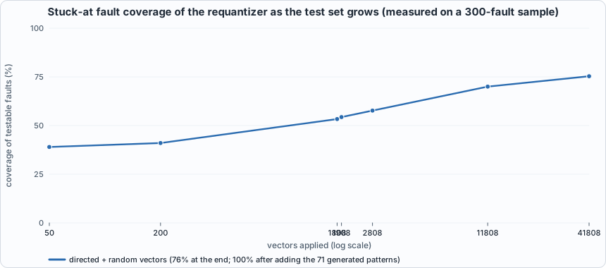 Figure 10.7 (measured): the coverage curve is steep at first and then nearly flat. Closing the last 24% took 71 specific vectors from the equivalence checker.
Running example A: how fast can an adder be?
The point of this example: the whole chapter's timing story rests on one fact, that a long chain of dependent gates is slow. The adder is the cleanest place to see it, and to see a choice a designer actually has. This example synthesizes adders of width 4 to 64 in three styles to the toy library and times each with the book's analyzer: a + b (let the tool choose), a hand-built ripple-carry chain (Chapter 1's design), and a Kogge-Stone parallel-prefix adder, which computes every carry in log2(width) levels. The three are first proved equal to a + b on all 65,536 pairs of 8-bit inputs in both simulators.
// Chapter 10, running example A: two adders of any width. demo_add writes "+" and lets the synthesis tool choose the structure; demo_ripple builds a chain of full adders by hand (the Chapter 1 ripple-carry design).
module demo_add #(parameter W = 8) (input [W-1:0] a, input [W-1:0] b, output [W:0] s);
    assign s = a + b;
endmodule
module demo_ripple #(parameter W = 8) (input [W-1:0] a, input [W-1:0] b, output [W:0] s);
    wire [W:0] c; assign c[0] = 1'b0;
    genvar i;
    generate for (i = 0; i < W; i = i + 1) begin : fa
        assign s[i] = a[i] ^ b[i] ^ c[i];
        assign c[i+1] = (a[i] & b[i]) | (c[i] & (a[i] ^ b[i]));
    end endgenerate
    assign s[W] = c[W];
endmodule
// A parallel-prefix (Kogge-Stone) adder for W a power of two: the carry into every bit is computed in log2(W) levels instead of rippling through W stages.
//   g = a & b (this bit generates a carry), p = a ^ b (this bit propagates one). Level k combines each bit's (g, p) with that of the bit 2^k places below: G' = G | (P & G_below), P' = P & P_below.
module demo_kogge #(parameter W = 8) (input [W-1:0] a, input [W-1:0] b, output [W:0] s);
    localparam LV = $clog2(W);
    wire [W-1:0] G [0:LV]; wire [W-1:0] P [0:LV];
    assign G[0] = a & b; assign P[0] = a ^ b;
    genvar l, i;
    generate for (l = 0; l < LV; l = l + 1) begin : lvl
        for (i = 0; i < W; i = i + 1) begin : bit_
            if (i >= (1 << l)) begin : comb
                assign G[l+1][i] = G[l][i] | (P[l][i] & G[l][i - (1 << l)]);
                assign P[l+1][i] = P[l][i] & P[l][i - (1 << l)];
            end else begin : pass
                assign G[l+1][i] = G[l][i]; assign P[l+1][i] = P[l][i];
            end
        end
    end endgenerate
    assign s[0] = P[0][0];
    generate for (i = 1; i < W; i = i + 1) begin : sm assign s[i] = P[0][i] ^ G[LV][i-1]; end endgenerate
    assign s[W] = G[LV][W-1];
endmodule
#!/usr/bin/env python3
"""Chapter 10, running example A: how does an adder's delay grow with its width? A 4-bit adder is synthesized to the toy library and its netlist read gate by gate; then adders of width 4 to 64, written three ways ("+", a hand-built ripple chain, and a Kogge-Stone parallel-prefix adder), are synthesized and timed by the book's static timing analyzer. Everything is MEASURED with the toy library (areas in NAND2 equivalents, one made-up delay per cell): the shape of the curves is the lesson, not the nanoseconds. Writes out/ch10_example_a.json. Usage: ch10_example_a.py"""
import json, os, re, sys
sys.path.insert(0, os.path.dirname(os.path.abspath(__file__))); import hw, synth
R = hw.ROOT; res = {"W": [], "plus": [], "ripple": [], "kogge": []}
def wrap(kind, W):
    top = f"{kind}_w{W}"; open(os.path.join(R, "out", top + ".v"), "w").write(f"module {top}(input [{W-1}:0] a, input [{W-1}:0] b, output [{W}:0] s); demo_{kind} #(.W({W})) u(.*); endmodule\n"); return top
print("== 1. the 4-bit adder through the flow (written with '+')")
top = wrap("add", 4); s = synth.synth(["rtl/demo_add.v", f"out/{top}.v"], top, top); t = synth.sta(os.path.join(R, "out", top + "_net.json"), top)
print(f"cells {s['ncells']}, area {s['area']:.1f} NAND2-equivalents, cell types {dict(sorted(s['cells'].items()))}")
print(f"critical path {t['critical_ns']:.2f} ns, {t['depth']} gates deep, ends at {t['endpoint']}")
print("\nthe netlist (out/%s_net.v), reduced to its gates:" % top)
net = open(os.path.join(R, "out", top + "_net.v")).read()
for m in re.finditer(r"^\s*(\w+) (\S+) \(\n((?:\s+\.\w+\([^)]*\),?\n)+)\s*\);", net, re.M): print("  ", m.group(1), " ".join(x.strip() for x in m.group(3).split("\n") if x.strip()))
print("\n== 2. delay and area against width, three styles; critical path in ns from the static timing analyzer (gate depth in brackets)")
print("   W |   '+' ns (gates) area |  ripple ns (gates) area | Kogge-Stone ns (gates) area")
for W in (4, 8, 16, 32, 64):
    row = {}
    for kind in ("add", "ripple", "kogge"):
        tp = wrap(kind, W); sy = synth.synth(["rtl/demo_add.v", f"out/{tp}.v"], tp, tp); ti = synth.sta(os.path.join(R, "out", tp + "_net.json"), tp); row[kind] = (ti["critical_ns"], ti["depth"], sy["area"])
    res["W"].append(W); res["plus"].append(row["add"]); res["ripple"].append(row["ripple"]); res["kogge"].append(row["kogge"])
    f = lambda r: f"{r[0]:6.2f} ({r[1]:2d}) {r[2]:6.0f}"
    print(f"{W:4d} | {f(row['add'])} | {f(row['ripple'])} | {f(row['kogge'])}")
p, q, k = res["plus"], res["ripple"], res["kogge"]
print(f"\nfrom 4 to 64 bits (16x wider): ripple delay x{q[-1][0]/q[0][0]:.1f}, area x{q[-1][2]/q[0][2]:.1f};  tool '+' delay x{p[-1][0]/p[0][0]:.1f}, area x{p[-1][2]/p[0][2]:.1f};  Kogge-Stone delay x{k[-1][0]/k[0][0]:.1f}, area x{k[-1][2]/k[0][2]:.1f}.")
print(f"at 64 bits Kogge-Stone is {q[-1][0]/k[-1][0]:.1f}x faster than the ripple chain and {k[-1][2]/q[-1][2]:.1f}x its area.")
print("OBSERVATION: Yosys's default flow turned '+' into a ripple chain (the '+' and ripple columns agree to within rounding). A faster adder has to be asked for or written; the tool does not pick one on its own here.")
print("a ripple chain's delay is proportional to its width (the carry passes through every stage, Chapter 1); a prefix adder's grows with log2(width), at the price of area.")
json.dump(res, open(os.path.join(R, "out", "ch10_example_a.json"), "w"))
To compile and run: python3 tools/ch10_example_a.py (about a minute; it runs Yosys 30 times). The correctness check is iverilog -g2012 -s demo_add_tb rtl/demo_add.v tb/demo_add_tb.v && vvp -n a.out (PASS on all 65,536 pairs in both Icarus and Verilator).
Output (cloud sandbox -- live-executed; Yosys 0.33, toy library)
== 1. the 4-bit adder through the flow (written with '+')
cells 17, area 26.7 NAND2-equivalents, cell types {'AND2': 1, 'AOI21': 1, 'NAND2': 3, 'NOR2': 2, 'OAI21': 2, 'OR2': 1, 'XNOR2': 4, 'XOR2': 3}
critical path 0.57 ns, 4 gates deep, ends at output s

the netlist (out/add_w4_net.v), reduced to its gates:
   NAND2 .A(a[0]), .B(b[0]), .Y(_00_)
   NAND2 .A(a[1]), .B(b[1]), .Y(_01_)
   NOR2 .A(a[1]), .B(b[1]), .Y(_02_)
   XOR2 .A(a[1]), .B(b[1]), .Y(_03_)
   XNOR2 .A(_00_), .B(_03_), .Y(s[1])
   OAI21 .A(_00_), .B(_02_), .C(_01_), .Y(_04_)
   AND2 .A(a[2]), .B(b[2]), .Y(_05_)
   OR2 .A(a[2]), .B(b[2]), .Y(_06_)
   XNOR2 .A(a[2]), .B(b[2]), .Y(_07_)
   XNOR2 .A(_04_), .B(_07_), .Y(s[2])
   AOI21 .A(_04_), .B(_06_), .C(_05_), .Y(_08_)
   NAND2 .A(a[3]), .B(b[3]), .Y(_09_)
   NOR2 .A(a[3]), .B(b[3]), .Y(_10_)
   XOR2 .A(a[3]), .B(b[3]), .Y(_11_)
   XNOR2 .A(_08_), .B(_11_), .Y(s[3])
   XOR2 .A(a[0]), .B(b[0]), .Y(s[0])
   OAI21 .A(_08_), .B(_10_), .C(_09_), .Y(s[4])

== 2. delay and area against width, three styles; critical path in ns from the static timing analyzer (gate depth in brackets)
   W |   '+' ns (gates) area |  ripple ns (gates) area | Kogge-Stone ns (gates) area
   4 |   0.57 ( 4)     27 |   0.57 ( 4)     27 |   0.57 ( 4)     27
   8 |   1.01 ( 8)     59 |   1.01 ( 8)     59 |   1.01 ( 8)     59
  16 |   1.89 (16)    123 |   1.89 (16)    123 |   1.76 (14)    148
  32 |   3.65 (32)    251 |   3.65 (32)    251 |   2.30 (19)    364
  64 |   7.13 (64)    506 |   7.17 (64)    507 |   2.22 (19)    923

from 4 to 64 bits (16x wider): ripple delay x12.6, area x19.0;  tool '+' delay x12.5, area x19.0;  Kogge-Stone delay x3.9, area x34.6.
at 64 bits Kogge-Stone is 3.2x faster than the ripple chain and 1.8x its area.
OBSERVATION: Yosys's default flow turned '+' into a ripple chain (the '+' and ripple columns agree to within rounding). A faster adder has to be asked for or written; the tool does not pick one on its own here.
a ripple chain's delay is proportional to its width (the carry passes through every stage, Chapter 1); a prefix adder's grows with log2(width), at the price of area.
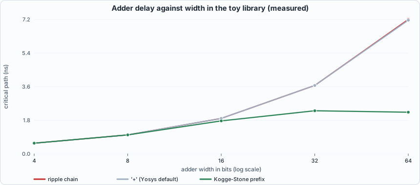 Figure 10.8 (measured): the ripple chain and the tool's
+ coincide and climb linearly; the prefix adder flattens.
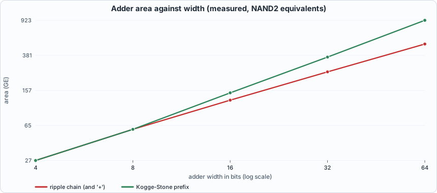 Figure 10.9 (measured): the price of speed. At 64 bits the prefix adder has 1.8 times the ripple chain's area.
Walkthrough.
- Reading a netlist. The 4-bit
+became 17 cells. Follow bit 1:NAND2(a1, b1)andXOR2(a1, b1)feed anXNOR2that makess[1]; the carry out of bit 1 isOAI21(_00_, _02_, _01_). That one OAI21 is the entire carry logic of the stage: it takesNAND(a0, b0)(the carry from bit 0),NOR(a1, b1)andNAND(a1, b1). Each stage's carry waits for the previous stage's, which is the ripple. - Delay is proportional to width for a ripple chain: 0.57, 1.01, 1.89, 3.65 and 7.13 ns for 4, 8, 16, 32 and 64 bits, almost exactly doubling with width.
- The tool's
+is that same chain. Yosys 0.33's default flow maps+to a ripple structure (its numbers equal the hand-built chain's within rounding). This is a finding about this flow; a commercial tool, or Yosys with other options, may do otherwise. The practical rule: do not assume the tool will make an adder fast. - The prefix adder. At 64 bits it is 2.22 ns against 7.17: 3.2 times faster, with 1.8 times the area (923 against 507 GE). Its delay grows by 3.9x for a 16-fold increase in width, against 12.6x for the ripple chain. It starts to win between 8 and 16 bits (the small-width numbers are equal).
- The lesson for the rest of the chapter. The requantizer's critical path is 79 gates deep, and a good share of that is two long ripple adders (the multiplier's final addition and the 57-bit rounding adder). Example B uses exactly this fix.
Running example B: pipelining the requantizer
The point of this example: the chip's clock is set by the requantizer (Figure 10.4). Real designs fix this by pipelining: put a register in the middle of the long path so that each half has a full clock period, at the price of an extra cycle of latency and some flip-flops. Here the requantizer is cut in two, proved correct, timed, and then improved a second time. It is an experiment with a surprise.
// Chapter 10, running example B: the Chapter 3 requantizer cut into two pipeline stages by one register. Stage 1 takes the magnitude of the accumulator and multiplies it by the mantissa (the big 32 x 24 multiplier); the register holds the 56-bit product and the few bits stage 2 still needs; stage 2 adds the rounding constant, shifts, clamps and restores the sign.
// Same function as `requant`, delayed by ONE clock cycle: the q that appears after clock edge n is the requantization of the inputs that were present just before it.
module rq_stage1 (input signed [31:0] acc, input [23:0] m, output neg, output [55:0] prod);
    assign neg = acc[31];
    wire [31:0] mag = neg ? (~acc + 32'd1) : acc;
    assign prod = mag * m;
endmodule
module rq_stage2 (input neg, input [55:0] prod, input [5:0] s, input relu, output signed [7:0] q);
    wire [55:0] half = (s == 6'd0) ? 56'd0 : (56'd1 << (s - 6'd1));
    wire [56:0] sum = {1'b0, prod} + {1'b0, half};
    wire [56:0] shifted = sum >> s;
    wire [6:0] mag_q = (shifted > 57'd127) ? 7'd127 : shifted[6:0];
    wire signed [7:0] signed_q = neg ? -$signed({1'b0, mag_q}) : $signed({1'b0, mag_q});
    assign q = (relu && signed_q[7]) ? 8'sd0 : signed_q;
endmodule
module requant_p2 (input clk, input signed [31:0] acc, input [23:0] m, input [5:0] s, input relu, output signed [7:0] q);
    wire neg1; wire [55:0] prod1; rq_stage1 u1 (.acc(acc), .m(m), .neg(neg1), .prod(prod1));
    reg neg_r; reg [55:0] prod_r; reg [5:0] s_r; reg relu_r;                       // the pipeline register: 64 flip-flops
    always @(posedge clk) begin neg_r <= neg1; prod_r <= prod1; s_r <= s; relu_r <= relu; end
    rq_stage2 u2 (.neg(neg_r), .prod(prod_r), .s(s_r), .relu(relu_r), .q(q));
endmodule

// Variant: the same two stages, but stage 2's 57-bit rounding addition is a Kogge-Stone prefix adder (rtl/demo_add.v) instead of the ripple chain the synthesis tool builds for "+".
module rq_stage2k (input neg, input [55:0] prod, input [5:0] s, input relu, output signed [7:0] q);
    wire [55:0] half = (s == 6'd0) ? 56'd0 : (56'd1 << (s - 6'd1));
    wire [56:0] sum; demo_kogge #(.W(56)) add (.a(prod), .b(half), .s(sum));
    wire [56:0] shifted = sum >> s;
    wire [6:0] mag_q = (shifted > 57'd127) ? 7'd127 : shifted[6:0];
    wire signed [7:0] signed_q = neg ? -$signed({1'b0, mag_q}) : $signed({1'b0, mag_q});
    assign q = (relu && signed_q[7]) ? 8'sd0 : signed_q;
endmodule
module requant_p2k (input clk, input signed [31:0] acc, input [23:0] m, input [5:0] s, input relu, output signed [7:0] q);
    wire neg1; wire [55:0] prod1; rq_stage1 u1 (.acc(acc), .m(m), .neg(neg1), .prod(prod1));
    reg neg_r; reg [55:0] prod_r; reg [5:0] s_r; reg relu_r;
    always @(posedge clk) begin neg_r <= neg1; prod_r <= prod1; s_r <= s; relu_r <= relu; end
    rq_stage2k u2 (.neg(neg_r), .prod(prod_r), .s(s_r), .relu(relu_r), .q(q));
endmodule
#!/usr/bin/env python3
"""Chapter 10, running example B: pipelining the requantizer, and learning where to cut. Chapter 10's chip-level timing report names one unit, the requantizer, as the one that sets the clock. Here it is improved in two steps, each MEASURED in the toy library: (1) cut in two by a register after the big multiplier (rtl/requant_p2.v); (2) the same cut, plus a parallel-prefix adder in stage 2 in place of the ripple chain the synthesis tool builds for "+" (Example A's lesson). Both are proved correct on the same 201,808 golden vectors in both simulators, with a one-cycle latency. Writes out/ch10_example_b.json. Usage: ch10_example_b.py"""
import json, os, subprocess, sys
sys.path.insert(0, os.path.dirname(os.path.abspath(__file__))); import hw, synth
R = hw.ROOT
subprocess.run([sys.executable, "model/requant_gold.py", "out/requant_vectors.hex"], cwd=R, capture_output=True)
print("== 1. correctness: both two-stage requantizers against the golden vectors used for the combinational one in Chapter 3 (one-cycle latency)")
for tb, files in (("requant_p2_tb", ["rtl/requant_p2.v", "tb/requant_p2_tb.v"]), ("requant_p2k_tb", ["rtl/demo_add.v", "rtl/requant_p2.v", "tb/requant_p2k_tb.v"])):
    for name, fn in (("Icarus", hw.sim_icarus), ("Verilator", hw.sim_verilator)):
        rc, out = fn(files, tb); print(f"  {tb:15s} {name:10s}", [l for l in out.splitlines() if l.startswith(("PASS", "FAIL", "MISMATCH"))][0], f"(exit {rc})")
print("\n== 2. timing and area, measured in the toy library (areas in NAND2 equivalents; delays in ns; every critical path includes the library's 0.30 ns clock-to-q and 0.10 ns setup where registers are involved)")
res = {}; F = ["rtl/demo_add.v", "rtl/requant.v", "rtl/requant_p2.v"]
print(f"{'design':36s} {'cells':>6s} {'area (GE)':>10s} {'flip-flops':>11s} {'critical path':>14s} {'gate depth':>11s} {'max clock':>10s}")
for label, top in (("combinational requant (Ch. 3)", "requant"), ("  stage 1 alone: abs + multiply", "rq_stage1"), ("  stage 2 alone: round, shift, clamp", "rq_stage2"), ("  stage 2 with prefix adder", "rq_stage2k"), ("two stages, cut after multiply", "requant_p2"), ("two stages + prefix adder", "requant_p2k")):
    s = synth.synth(F, top, "b_" + top); t = synth.sta(os.path.join(R, "out", f"b_{top}_net.json"), top); ff = s["cells"].get("DFF", 0)
    res[top] = {"ns": t["critical_ns"], "area": s["area"], "ff": ff, "depth": t["depth"], "cells": s["ncells"]}
    print(f"{label:36s} {s['ncells']:6d} {s['area']:10.0f} {ff:11d} {t['critical_ns']:11.2f} ns {t['depth']:11d} {1000/t['critical_ns']:7.0f} MHz")
a, b, c, ck, d, dk = (res[k] for k in ("requant", "rq_stage1", "rq_stage2", "rq_stage2k", "requant_p2", "requant_p2k"))
print(f"\nstep 1, cut after the multiplier: {a['ns']:.2f} -> {d['ns']:.2f} ns, only {a['ns']/d['ns']:.2f}x. The cut is unbalanced: stage 1 (the multiplier) is {b['ns']:.2f} ns but stage 2 is {c['ns']:.2f} ns, 72 gates deep for what looks like 'an add, a shift and a clamp'.")
print(f"        Why: stage 2's 57-bit addition is a RIPPLE chain (Example A: Yosys maps '+' to one), and the carry passes through ~57 gates.")
print(f"step 2, replace that adder by a prefix adder: stage 2 falls from {c['ns']:.2f} to {ck['ns']:.2f} ns; the whole two-stage design from {d['ns']:.2f} to {dk['ns']:.2f} ns, {a['ns']/dk['ns']:.2f}x faster than the original")
print(f"        for {dk['ff']} flip-flops and {dk['area']-a['area']:+.0f} GE ({100*(dk['area']/a['area']-1):+.1f}% area) and one cycle of latency. Now stage 1 ({b['ns']:.2f} ns, the multiplier) is the limit: to go further the multiplier itself must be pipelined or restructured.")
print("\nNOTE: ABC maps every synthesis run separately, so a block's delay differs by a few percent between standalone and inside a larger design (stage 1 reads 8.23 ns alone and about 7.7 ns inside requant_p2); read differences of several percent as noise and the large steps as real.")
print("\n== 3. what this would do to the whole chip (an ESTIMATE from Chapter 10's table of unit timings, not a re-synthesis of the chip)")
print("the chip's critical path was 10.74 ns through the requantizer (scratchpad read -> requant -> scratchpad write). The next slowest units: the matrix unit at 5.94 ns, the softmax at 5.03 ns.")
print(f"With the requantizer at {dk['ns']:.2f} ns it is STILL the slowest block in the chip and sets the clock: about {10.74*dk['ns']/a['ns']:.2f} ns (scaling the chip's path by the unit's improvement), {10.74/(10.74*dk['ns']/a['ns']):.2f}x faster.")
print("Reaching the next unit (about 6 ns) would need a third stage inside the multiplier. Chapter 7's cycle model gives RQ n + 2 cycles; each added stage adds one cycle per RQ instruction.")
json.dump(res, open(os.path.join(R, "out", "ch10_example_b.json"), "w"))
To compile and run: python3 tools/ch10_example_b.py (about a minute). It first regenerates the 201,808 golden vectors of Chapter 3 and runs both pipelined designs against them (one-cycle latency) in both simulators.
Output (cloud sandbox -- live-executed; Yosys 0.33, toy library)
== 1. correctness: both two-stage requantizers against the golden vectors used for the combinational one in Chapter 3 (one-cycle latency)
  requant_p2_tb   Icarus     PASS: the two-stage requantizer matches the golden model on all 201808 cases (exit status 0) (exit 0)
  requant_p2_tb   Verilator  PASS: the two-stage requantizer matches the golden model on all 201808 cases (exit status 0) (exit 0)
  requant_p2k_tb  Icarus     PASS: the two-stage requantizer with a prefix adder matches the golden model on all 201808 cases (exit status 0) (exit 0)
  requant_p2k_tb  Verilator  PASS: the two-stage requantizer with a prefix adder matches the golden model on all 201808 cases (exit status 0) (exit 0)

== 2. timing and area, measured in the toy library (areas in NAND2 equivalents; delays in ns; every critical path includes the library's 0.30 ns clock-to-q and 0.10 ns setup where registers are involved)
design                                cells  area (GE)  flip-flops  critical path  gate depth  max clock
combinational requant (Ch. 3)          5403       7881           0        9.87 ns          79     101 MHz
  stage 1 alone: abs + multiply        4412       6451           0        8.23 ns          64     122 MHz
  stage 2 alone: round, shift, clamp    829       1266           0        8.39 ns          72     119 MHz
  stage 2 with prefix adder            1044       1599           0        4.76 ns          38     210 MHz
two stages, cut after multiply         5353       7991          64        8.90 ns          71     112 MHz
two stages + prefix adder              5466       8188          64        7.82 ns          61     128 MHz

step 1, cut after the multiplier: 9.87 -> 8.90 ns, only 1.11x. The cut is unbalanced: stage 1 (the multiplier) is 8.23 ns but stage 2 is 8.39 ns, 72 gates deep for what looks like 'an add, a shift and a clamp'.
        Why: stage 2's 57-bit addition is a RIPPLE chain (Example A: Yosys maps '+' to one), and the carry passes through ~57 gates.
step 2, replace that adder by a prefix adder: stage 2 falls from 8.39 to 4.76 ns; the whole two-stage design from 8.90 to 7.82 ns, 1.26x faster than the original
        for 64 flip-flops and +307 GE (+3.9% area) and one cycle of latency. Now stage 1 (8.23 ns, the multiplier) is the limit: to go further the multiplier itself must be pipelined or restructured.

NOTE: ABC maps every synthesis run separately, so a block's delay differs by a few percent between standalone and inside a larger design (stage 1 reads 8.23 ns alone and about 7.7 ns inside requant_p2); read differences of several percent as noise and the large steps as real.

== 3. what this would do to the whole chip (an ESTIMATE from Chapter 10's table of unit timings, not a re-synthesis of the chip)
the chip's critical path was 10.74 ns through the requantizer (scratchpad read -> requant -> scratchpad write). The next slowest units: the matrix unit at 5.94 ns, the softmax at 5.03 ns.
With the requantizer at 7.82 ns it is STILL the slowest block in the chip and sets the clock: about 8.51 ns (scaling the chip's path by the unit's improvement), 1.26x faster.
Reaching the next unit (about 6 ns) would need a third stage inside the multiplier. Chapter 7's cycle model gives RQ n + 2 cycles; each added stage adds one cycle per RQ instruction.
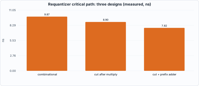 Figure 10.10 (measured): three versions of the requantizer.
Walkthrough.
- Correctness first. Both pipelined versions match the golden vectors on all 201,808 cases in Icarus and Verilator, with the one-cycle latency the testbench allows for. A change that makes a unit faster has to pass the same tests as the original, and does.
- The first cut disappoints. Putting the register after the multiplier gives 8.90 ns against 9.87: only 1.11x faster. Looking at the two halves separately explains why: stage 1 (the multiplier) is 8.23 ns, but stage 2 is 8.39 ns and 72 gates deep, although all it does is add a constant, shift and clamp.
- The reason is a ripple chain. Stage 2's 57-bit addition is built by Yosys as a ripple chain (Example A). Replacing it with a Kogge-Stone adder takes stage 2 from 8.39 to 4.76 ns, and the whole two-stage design to 7.82 ns, 1.26x faster than the original, for 64 flip-flops and about 4% more area, plus one cycle of latency per requantization.
- What is left. Now stage 1, the multiplier (about 8 ns), is the limit. Going further means pipelining inside the multiplier or choosing a different multiplier structure. Each added stage costs a cycle of latency per
RQand 64-odd flip-flops. - The whole chip (an estimate, not a re-synthesis). The chip's 10.47 ns path goes scratchpad read, requantizer, scratchpad write. If only the requantizer improves by 1.26x, scaling that path gives about 8.3 ns: still the slowest block in the chip. To reach the next-slowest unit (the matrix unit at 5.9 ns) the requantizer would need a third stage. (An earlier version of this page said that a single cut would reach 5 to 6 ns. The experiment shows that was too optimistic.)
- A caveat about noise. ABC maps each synthesis run separately, so a block's delay changes by a few percent between standalone and inside a bigger design. Read the 1.11x and 1.26x as the right order of magnitude, not as exact figures.
- The cost to the program. Chapter 7's cycle model gives
RQon n words as n + 2 cycles; a two-stage requantizer makes it n + 3. A program with R requantize instructions loses R cycles in total, tiny against thousands of cycles of work, in exchange for a clock about a quarter shorter.
Testing the tests of the flow
The flow itself can be wrong: the library description that synthesis reads can disagree with the simulation models. The mutation script gives synthesis a wrong function for one cell at a time and checks that gate-level simulation of the requantizer notices.
#!/usr/bin/env python3
"""Chapter 10: test the tests of the FLOW. Break one cell function in the library description that synthesis reads (the simulation models stay correct), re-synthesize the requantizer, and run the gate-level simulation
against the golden vectors. If synthesis used the wrong function, the netlist is wrong, and the simulation must fail. A cell the mapper never uses cannot matter (reported as such)."""
import concurrent.futures, os, re, subprocess, sys
sys.path.insert(0, os.path.dirname(os.path.abspath(__file__))); import hw, synth
R = hw.ROOT; LIB = open(os.path.join(R, "lib", "toy.lib")).read()
subprocess.run([sys.executable, "model/requant_gold.py", "out/requant_vectors.hex", "3000"], cwd=R, capture_output=True)
MUT = [("XOR2", '"(A^B)"', '"!(A^B)"'), ("XNOR2", '"!(A^B)"', '"(A^B)"'), ("NAND2", '"!(A&B)"', '"(A&B)"'), ("NOR2", '"!(A|B)"', '"(A|B)"'), ("INV", 'function : "!A"', 'function : "A"'),
       ("MUX2", '"((S&B)|(!S&A))"', '"((S&A)|(!S&B))"'), ("AOI21", '"!((A&B)|C)"', '"!((A|B)&C)"'), ("OAI21", '"!((A|B)&C)"', '"!((A&B)|C)"'), ("NAND3", '"!(A&B&C)"', '"!(A&B)"'),
       ("NOR3", '"!(A|B|C)"', '"!(A|B)"'), ("AND2", '"(A&B)"', '"(A|B)"'), ("OR2", '"(A|B)"', '"(A&B)"'), ("BUF", 'function : "A"', 'function : "!A"')]
def one(i):
    cell, old, new = MUT[i]; m = re.search(r"cell\(%s\) \{.*?\n  \}" % cell, LIB, re.S); body = m.group(0)
    if old not in body: return cell, "BAD ANCHOR"
    lib = LIB.replace(body, body.replace(old, new, 1)); path = f"out/badlib_{cell}.lib"; open(os.path.join(R, path), "w").write(lib)
    s = synth.synth(["rtl/requant.v"], "requant", f"badflow_{cell}", lib=path)
    if not s["ok"]: return cell, "synthesis failed (caught at synthesis)"
    used = s["cells"].get(cell, 0)
    rc, out = hw.sim_icarus(["lib/toy_cells.v", f"out/badflow_{cell}_net.v", "tb/requant_tb.v"], "requant_tb")
    return cell, ("caught" if rc != 0 or "PASS" not in out else "NOT CAUGHT") + f"   (the mapper used {used} {cell} cells)"
print("NOTE: this script deliberately mis-describes one cell to the synthesis tool. 'caught' lines are EXPECTED: gate-level simulation notices the wrong logic.")
with concurrent.futures.ThreadPoolExecutor(max_workers=4) as pool: rows = list(pool.map(one, range(len(MUT))))
for cell, r in rows: print(f"library says {cell} computes the wrong function: {r}")
Output (cloud sandbox -- live-executed)
NOTE: this script deliberately mis-describes one cell to the synthesis tool. 'caught' lines are EXPECTED: gate-level simulation notices the wrong logic.
library says XOR2 computes the wrong function: NOT CAUGHT   (the mapper used 0 XOR2 cells)
library says XNOR2 computes the wrong function: caught   (the mapper used 1298 XNOR2 cells)
library says NAND2 computes the wrong function: caught   (the mapper used 1216 NAND2 cells)
library says NOR2 computes the wrong function: caught   (the mapper used 274 NOR2 cells)
library says INV computes the wrong function: synthesis failed (caught at synthesis)
library says MUX2 computes the wrong function: caught   (the mapper used 142 MUX2 cells)
library says AOI21 computes the wrong function: caught   (the mapper used 275 AOI21 cells)
library says OAI21 computes the wrong function: NOT CAUGHT   (the mapper used 0 OAI21 cells)
library says NAND3 computes the wrong function: NOT CAUGHT   (the mapper used 0 NAND3 cells)
library says NOR3 computes the wrong function: NOT CAUGHT   (the mapper used 0 NOR3 cells)
library says AND2 computes the wrong function: caught   (the mapper used 126 AND2 cells)
library says OR2 computes the wrong function: NOT CAUGHT   (the mapper used 0 OR2 cells)
library says BUF computes the wrong function: synthesis failed (caught at synthesis)
Every wrong function that the mapper actually used is caught: XNOR2, NAND2, NOR2, MUX2, AOI21 and AND2 (the mapper used between 126 and 1,298 of each) fail the simulation, and the INV and BUF mistakes break synthesis itself. Five survive and each is an equivalent mutant of the flow: the mapper used zero XOR2, OAI21, NAND3, NOR3 and OR2 cells for this design, so a wrong description of them cannot change the netlist. (It would for another design. The check is only as broad as the circuit it runs on.)
Common mistakes
- Reading a gate count as a speed. Cell counts are area; speed is the longest path. Two adders with equal area can differ by a factor of three in delay.
- Assuming the tool picks the fast structure. Yosys's default
+is a ripple chain (Example A). Check the netlist or the timing, and ask for the structure you want. - Pipelining at the wrong place. The first cut of Example B improved the clock by 11%. Time the halves separately before deciding where the register goes.
- Forgetting that pipelining changes latency. The pipelined requantizer is correct only if everything around it expects its result one cycle later (the testbench, the sequencer, the cycle model).
- Trusting a four-state simulation of a netlist from reset-less flops. X-pessimism makes a correct netlist fail; start from a defined state, or reset.
- Treating coverage by random vectors as proof. 41,808 vectors found 76% of the gate-level faults; an equivalence checker found the rest.
- Taking toy-library numbers as predictions. They compare designs against each other; they say nothing about any real process.
What this chapter does and does not establish
- Established: GA-2 synthesizes to 31,580 cells plus macros; the netlist runs all 78 programs with identical memory and cycle counters; it also passes from three random power-up states; a wrong cell description is caught whenever the design uses the cell; stuck-at fault coverage of the requantizer sample goes from 76% to 100% with generated patterns.
- Not established: anything about a real process. The areas and delays are those of a toy library; there is no place-and-route, wire delay, clock tree, power analysis or manufacturing test flow. The timing analyzer is a model. Formal equivalence was shown on the requantizer's faults, not between the RTL and the netlist of the whole chip.
Chapter summary
Synthesis maps the RTL onto a cell library; area and a longest-path timing figure follow from the netlist (here 53,526 NAND2 equivalents and a 10.5 ns critical path through the requantizer, which is the unit to pipeline). The netlist passes the same program suite as the RTL, but a four-state simulator needs a defined power-up state to avoid X-pessimism, and random power-up testing exposed a stray-response bug in the testbench. Fault grading shows that a suite that finds every RTL mutant still detects only 76% of gate-level faults, and equivalence checking both classifies the rest and generates the missing tests.
Self-check questions
- Why does the toy library come with two files generated from one table?
- The critical path of the chip is
sp.rdata -> ... -> sp.wdata. Which unit is on it, and what would you change? - What is X-pessimism, and what evidence shows that the Icarus failure was not a logic error?
- Why did the first random power-up run produce
deadbeefin the data, and who was at fault? - What does it mean that 3 faults were "proven redundant", and why is detecting them not a goal?
- A path has a flip-flop (clock-to-q 0.30), gates of delay 0.07, 0.16, 0.11 and 0.04, and a setup of 0.10. What is the shortest clock period this path allows?
- In Running example A the 64-bit prefix adder is 3.2 times faster than the ripple chain with 1.8 times the area. If the adder were on the critical path of a design that is 20% adder and 80% other logic at the same clock, how much faster could the whole design clock?
- Why does Running example B's first cut (after the multiplier) improve the clock by only 11%?
Exercises
- Another width. Run Example A for width 12 and 24 (not powers of two). Does the Kogge-Stone design still work (it passes the 8-bit exhaustive test; try your own check at 12 bits with random inputs) and where does it land between its neighbours?
- Add a stage. In
requant_p2.v, add a second pipeline register that splits stage 1 (for example, register the magnitude before the multiplier). Predict whether that helps, then measure. What is the new latency ofRQ? - Another library. Change the delay of XOR2 in
tools/gen_toylib.pyto 0.30 ns (a slow XOR) and rerun Example A. Which adder style is hurt most, and why? - Balanced cuts. Find the best position for a single register in the combinational requantizer by trying three cuts of your own design (for example, after the rounding addition). Report the critical path of each.
- Reset everything. Add a reset to every flip-flop of the Chapter 7 chip's units (or just to
ga2_rq), resynthesize and compare area with the X-pessimism fix the book uses. What does "reset everything" cost?